Ford Escape 2020-2026 Service Manual / Powertrain / Engine / Fuel Charging and Controls - Turbocharger - 2.0L EcoBoost (177kW/240PS) – MI4 / Removal and Installation - Turbocharger Coolant Supply Tube
Ford Escape: Fuel Charging and Controls - Turbocharger - 2.0L EcoBoost (177kW/240PS) – MI4 / Removal and Installation - Turbocharger Coolant Supply Tube
Removal and Installation
NOTICE: The turbocharger compressor vanes can be damaged by even the smallest particles. When removing any turbocharger or engine air intake system component, ensure that no debris enters the system. Failure to do so may result in damage to the turbocharger.
NOTICE: Special attention needs to be given to the sealing ports for the oil supply, the oil return, and the coolant tubes, on turbocharged engines. The sealing ports must be totally clean and free from O-ring residue, have no damage to the sealing surface and the tubes to ensure that there are no leaks or repeat repairs.
-
The turbocharger coolant supply tube is removed in the turbocharger procedure.
Refer to: Turbocharger (303-04E Fuel Charging and Controls - Turbocharger - 2.0L EcoBoost (177kW/240PS) – MI4, Removal and Installation).
 Removal and Installation - Turbocharger Coolant Return Tube
Removal and Installation
NOTICE:
The turbocharger compressor vanes can be damaged by even the
smallest particles. When removing any turbocharger or engine air intake
system component, ensure that no debris enters the system...
 Removal and Installation - Turbocharger Oil Return Tube
Materials
Name
Specification
Motorcraft® Metal Brake Parts CleanerPM-4-A, PM-4-B, APM-4-C
-
Removal
NOTICE:
The turbocharger compressor vanes can be damaged by even the
smallest particles...
Other information:
Ford Escape 2020-2026 Owners Manual: Automatic High Beam Control
How Does Automatic High Beam Control Work Automatic high beam control turns the high beams on if it is dark enough and no other traffic is present. If it detects an approaching vehicle’s headlamps or tail lamps, or street lighting ahead, the system turns the high beams off...
Ford Escape 2020-2026 Owners Manual: Grade Assist - Hybrid Electric Vehicle (HEV)
What Is Grade Assist Provides additional grade braking with a combination of engine motoring and high-voltage battery charging to help maintain vehicle speed when descending a grade. Switching Grade Assist On and Off Press the grade assist button to activate grade assist...
Categories
- Manuals Home
- 4th Generation Ford Escape Owners Manual
- 4th Generation Ford Escape Service Manual
- Plug-In Hybrid Electric Vehicle Drive Modes
- Switching the Lane Keeping System On and Off. Switching the Lane Keeping System Mode. Alert Mode
- All-Wheel Drive
- New on site
- Most important about car
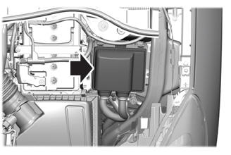
Under Hood Fuse Box
Locating the Under Hood Fuse Box

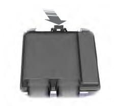
Accessing the Under Hood Fuse Box

Copyright © 2026 www.fordescape4.com
