Ford Escape: Rear Suspension / Removal and Installation - Wheel Knuckle - AWD
Special Tool(s) / General Equipment
| Vehicle/Axle Stands |
Removal
NOTICE: Suspension fasteners are critical parts that affect the performance of vital components and systems. Failure of these fasteners may result in major service expense. Use the same or equivalent parts if replacement is necessary. Do not use a replacement part of lesser quality or substitute design. Tighten fasteners as specified.
-
Remove the brake disc shield.
Refer to: Brake Disc Shield (206-04 Rear Disc Brake, Removal and Installation).
-
-
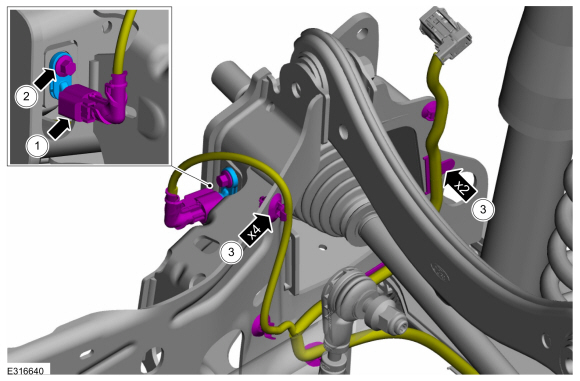
Disconnect the wheel speed sensor electrical connector.
-
NOTE: Make sure that the sensor housing area is clean and free of foreign material before the sensor is removed.
NOTE: This step is only necessary when installing a new component.
Remove the wheel speed sensor bolt and position aside the wheel speed sensor.
-
Unclip the rear wire harness retaining clips and position the harness aside.
-
Disconnect the wheel speed sensor electrical connector.
 |
-
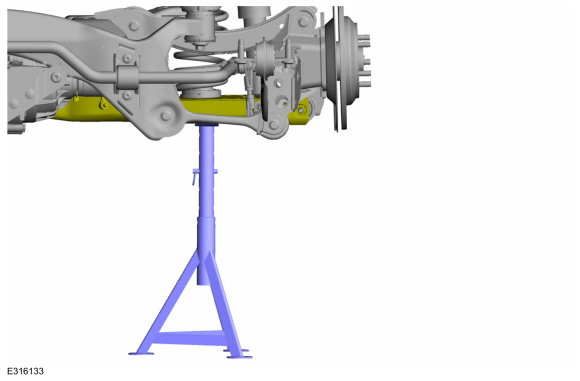
NOTICE: Do not attempt to jacking on the front control arm or rear control arm on any vehicle. Damage to control arms may occur.
NOTICE: Make sure that the insulator pads are correctly positioned to prevent direct contact with other components.
Support the rear suspension to ride height.
Use the General Equipment: Vehicle/Axle Stands
 |
-
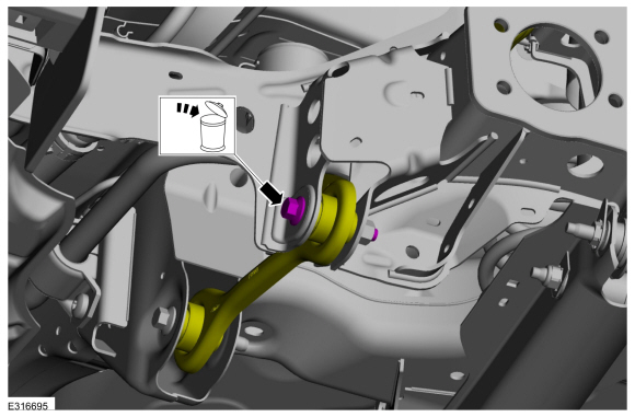
NOTICE: Do not use power tools to remove the stabilizer bar link nut. Damage to the stabilizer bar link ball joint or boot may occur.
NOTE: The stabilizer bar links are designed with low friction ball joints that have a low breakaway torque.
NOTE: Use the TORX PLUS® holding feature to prevent the ball stud from turning while removing or installing the lower arm outboard nut. Torx® and TORX PLUS® is a reg. tm of Acument Intellectual Properties, LLC.
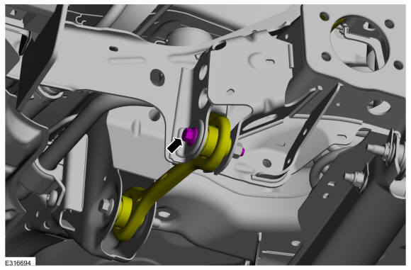
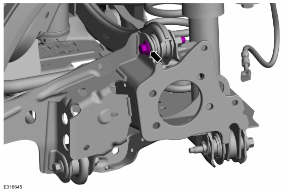
Remove and discard the rear tabilizer link lower nut and position aside.
 |
-
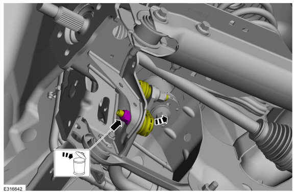
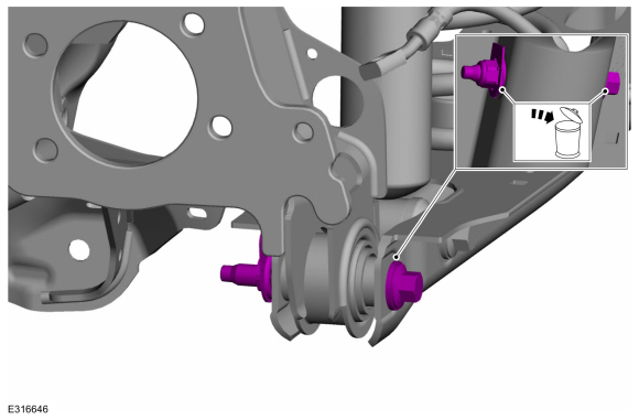
Remove and discard the upper arm-to-wheel knuckle bolt.
 |
-
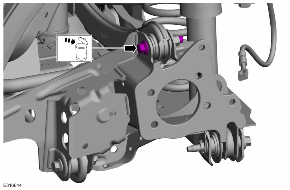
Remove and discard the rear lower arm-to-wheel knuckle bolt and nut.
 |
-
Remove and discard the front lower arm-to-wheel knuckle bolt.
 |
-
Remove the retainers and position aside the RH underbody shield.
 |
-
Remove the retainers and position aside the LH underbody shield.
 |
-
Remove and discard the wheel knuckle forward bolts and remove the wheel knuckle.
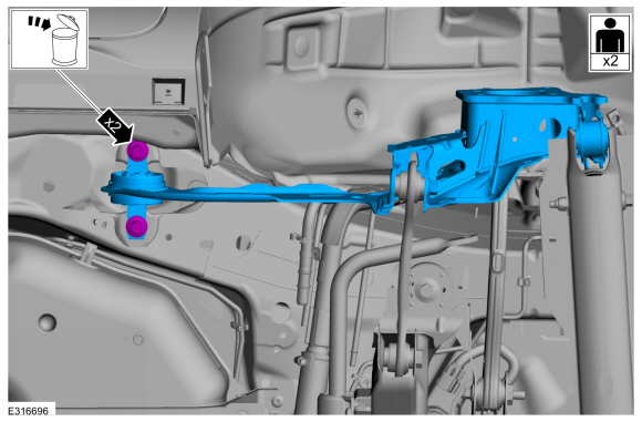 |
Installation
-
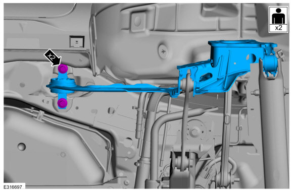
Install the wheel knuckle and tighten the new wheel knuckle forward bolts.
Torque: 129 lb.ft (175 Nm)
 |
-
Position the LH underbody shield and install the retainers.
Torque: 22 lb.in (2.5 Nm)
|
-
Position theRH underbody shield and install the retainers.
Torque: 22 lb.in (2.5 Nm)
|
-
NOTE: Only tighten the bolt and nut finger tight at this stage.
Install the new front lower arm-to-wheel knuckle bolt.
 |
-
NOTE: Only tighten the bolt and nut finger tight at this stage.
Install the new rear lower arm-to-wheel knuckle bolt and nut.
 |
-
NOTE: Only tighten the bolt and nut finger tight at this stage.
Install the new upper arm-to-wheel knuckle bolt.
 |
-
NOTICE: Do not attempt to jacking on the front control arm or rear control arm on any vehicle. Damage to control arms may occur.
NOTICE: Make sure that the insulator pads are correctly positioned to prevent direct contact with other components.
Raise the suspension to curb height.
Use the General Equipment: Vehicle/Axle Stands
|
-
NOTICE: Tighten the suspension fasteners with the weight of the vehicle on the wheels and tires or use a suitable jack to raise the suspension to curb height or damage to the bushings may occur.
Tighten the new front lower arm-to-wheel knuckle bolt.
Torque:
Stage 1: 59 lb.ft (80 Nm)
Stage 2: 120°
|
-
NOTICE: Tighten the suspension fasteners with the weight of the vehicle on the wheels and tires or use a suitable jack to raise the suspension to curb height or damage to the bushings may occur.
Tighten the new rear lower arm-to-wheel knuckle bolt and nut.
Torque:
Stage 1: 81 lb.ft (110 Nm)
Stage 2: 120°
|
-
NOTICE: Tighten the suspension fasteners with the weight of the vehicle on the wheels and tires or use a suitable jack to raise the suspension to curb height or damage to the bushings may occur.
Tighten the new upper arm-to-wheel knuckle bolt.
Torque:
Stage 1: 59 lb.ft (80 Nm)
Stage 2: 120°
|
-
NOTE: The stabilizer bar links are designed with low friction ball joints that have a low breakaway torque.
NOTE: Use the TORX PLUS® holding feature to prevent the ball stud from turning while removing or installing the lower arm outboard nut. Torx® and TORX PLUS® is a reg. tm of Acument Intellectual Properties, LLC.
Connect the rear stabilizer link to the wheel knuckle and install the new rear stabilizer link nut.
Torque: 85 lb.ft (115 Nm)
 |
-
NOTICE: Before installing a wheel speed sensor, inspect the sensor housing to make sure the sensor cavity is clean and free of foreign material or damage to the sensor may occur.
-
NOTE: This step is only necessary when installing a new component.
Install the wheel speed sensor and tighten the bolt.
Torque: 71 lb.in (8 Nm)
-
Connect the wheel speed sensor electrical connector.
-
Position the wire harness and clip the harness retaining clips into place.
-
 |
-
Install the brake disc shield.
Refer to: Brake Disc Shield (206-04 Rear Disc Brake, Removal and Installation).
-
Check and if necessary adjust rear toe.
Refer to: Rear Toe Adjustment (204-00 Suspension System - General Information, General Procedures).
 Removal and Installation - Wheel Bearing and Wheel Hub - FWD
Removal
NOTICE:
Suspension fasteners are critical parts that affect the
performance of vital components and systems. Failure of these fasteners
may result in major service expense...
 Removal and Installation - Wheel Knuckle - FWD
Special Tool(s) /
General Equipment
Vehicle/Axle Stands
Removal
NOTICE:
Suspension fasteners are critical parts that affect the
performance of vital components and systems...
Other information:
Ford Escape 2020-2026 Service Manual: Disassembly - Transmission
Special Tool(s) / General Equipment 307-163 (T86P-70043-A) Remover, Stator Case BearingTKIT-1986-LMTKIT-1986-F 307-586Differential bearing cup removerTKIT-2006UF-FLMTKIT-2006UF-ROW 307-741Spring Compressor, F Clutch 307-821Motor Rotor Remover Installer 308-001 (T58L-101-B) Remover, Pilot Bearing Hydraulic Press Puller Punch Wooden Block ..
Ford Escape 2020-2026 Service Manual: Removal and Installation - Hazard Flasher Switch
Removal NOTE: Removal steps in this procedure may contain installation details. Remove the center registers. Refer to: Center Registers (412-00 Climate Control System - General Information, Removal and Installation). Release the tabs and remove the hazard flasher switch from the center registers. Installation To install, reverse..
Categories
- Manuals Home
- 4th Generation Ford Escape Owners Manual
- 4th Generation Ford Escape Service Manual
- Rear View Camera
- Drive Modes
- Description and Operation - Identification Codes
- New on site
- Most important about car
Adjusting the Seatbelts During Pregnancy
WARNING: Always ride and drive with your seatback upright and properly fasten your seatbelt. Fit the lap portion of the seatbelt snugly and low across the hips. Position the shoulder portion of the seatbelt across your chest. Pregnant women must follow this practice. See the following figure.
