Ford Escape: Power Transfer Unit / Removal - Power Transfer Unit
Special Tool(s) /
General Equipment
-
Remove the front subframe.
Refer to: Front Subframe (502-00 Uni-Body, Subframe and Mounting System, Removal and Installation).
-
Drain the PTU.
Refer to: Power Transfer Unit Draining and Filling (308-07D)
.
-
Remove the intermediate shaft.
Refer to: Intermediate Shaft (205-04 Front Drive Halfshafts, Removal and Installation).
-
NOTE:
Clean the catalytic converter-to-muffler sealing surfaces.
-
Loosen the catalytic converter-to-muffler and tailpipe nut and separate.
-
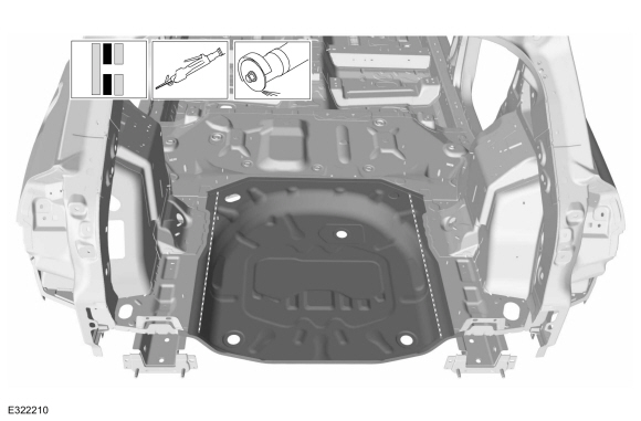
Position and support the muffler and tailpipe aside.
-
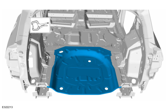
Remove the catalytic converter mounting bracket nuts and the catalytic converter mounting bracket.
-
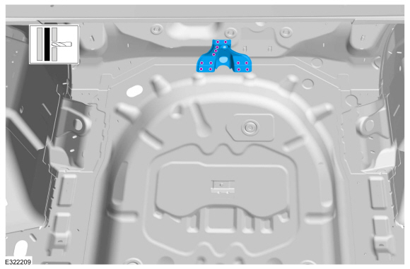
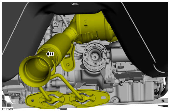
Remove and discard the driveshaft to PTU bolts and retaining straps.
Torque:
26 lb.ft (35 Nm)
-
Separate the driveshaft from the PTU flange.
-
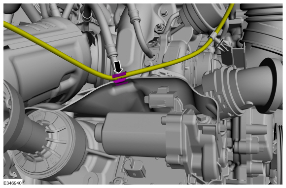
NOTE:
Make sure that the component aligns with the installation mark.
Index-mark the driveshaft and PTU flange.
-
NOTICE:
Do not remove driveshaft from the PTU flange by
pulling on the driveshaft tube. Damage to the CV-joint can result.
Using general equipment, separate the driveshaft from the PTU flange.
Use the General Equipment: Punch
Use the General Equipment: Copper Hammer
-
Position and support the driveshaft aside.
-
NOTE:
Do not pull the engine appearance cover forward or
sideways to remove. Failure to press straight upward on the underside of
the cover at the attachment points may result in damage to the cover or
engine components.
-
1.Remove the engine appearance cover nut.
-
2.Place your hand under the engine appearance cover at
each grommet location and push straight up to release each grommet from
the studs.
-
3.After all of the grommets have been released from the studs, remove the appearance cover from the engine.
-
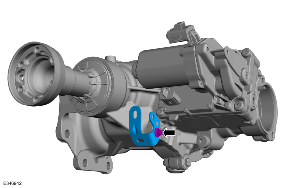
Disconnect and position aside the PTU vent hose.
-
Remove the vent hose retainer.
-
If equipped, disconnect the PTU temperature sensor
electrical connector. Disconnect the motor connectors and the retainers.
-
If equipped, disconnect retainer and position aside the wiring harness.
-
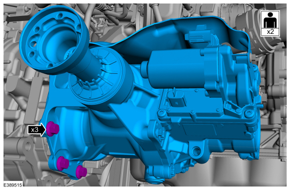
Remove the PTU support bracket bolts and the PTU support bracket.
-
NOTE:
Excessive bending of the exhaust flexible pipe may cause damage resulting in failure.
Secure exhaust flexible pipe.
-
-
Disconnect the HO2S connector and harness retainer.
-
Disconnect the catalyst monitor sensor connector and harness retainers.
-
Remove the EGR cooler inlet tube.
Refer to: Exhaust Gas Recirculation (EGR) Cooler Inlet Tube (303-08C Engine Emission Control, Removal and Installation).
-
Remove the bolts and the heat shield
-
Remove and discard the exhaust manifold nuts.
-
Position aside the catalytic converter.
-
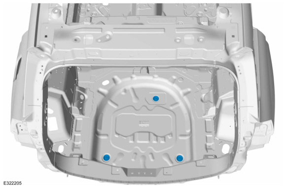
Remove the PTU bolts.
-
NOTICE:
This is a tight fit, use care to not damage the transmission and PTU mating surfaces.
Remove the PTU bolts and the PTU.
-
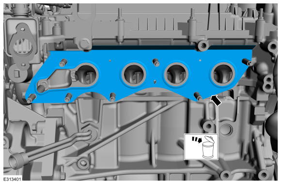
Remove and discard the PTU to transmission seal.
-
Remove and discard the gasket.
-
NOTE:
This step is only necessary when installing a new PTU or replacing a PTU seal.
Remove the PTU heat shield bolts and PTU heat shield.
Torque:
89 lb.in (10 Nm)
-
NOTE:
This step is only necessary when installing a new PTU or replacing a PTU seal.
If equipped, remove the PTU temperature sensor harness bracket.
Special Tool(s) /
General Equipment
205-199
(T83T-3132-A1)
Installer, Spindle/Axle ShaftT83-4000-ATKIT-1983-FTKIT-1983-FLMTKIT-1983-FX
308-777Remover and Installer, PTU Input Shaft Seal
308-969Installer, Pinion Seal
Slide Hammer Dent Puller
Plastic Mallet
Two Leg Puller
Removal
Remove the PTU...
NOTE:
This step is only necessary when installing a new PTU or replacing a PTU seal.
Install the PTU heat shield.
Torque:
89 lb.in (10 Nm)
NOTE:
This step is only necessary when installing a new PTU or replacing a PTU seal...
Other information:
Argentina
Brazil
Djibouti
European Union EU
Ghana
Jordan
Mauritania
Mexico
Moldova
Morocco
Nigeria
Oman
Pakistan
Paraguay
NR: 2018-06-I-000224
Philippines
Russia
Serbia
Singapore
South Africa
South Korea
R-CRM-SRD-AG2SM4
Taiwan
Ukraine
United Arab Emirates (U...
Special Tool(s) /
General Equipment
ROB75240Coolant/Battery Refractometer (Fahrenheit)
Fluid Container
Cooling System Vacuum Tester and Refiller
Draining
NOTICE:
The coolant must be recovered in a suitable, clean container
for reuse...
.jpg)
.jpg)
.jpg)
.jpg)
.jpg)
.jpg)
.jpg)
.jpg)
.jpg)
 Removal and Installation - Power Transfer Unit Rear Seal
 Installation - Power Transfer Unit