
Ford Escape: Automatic Transmission / Power Transfer Unit
- Specifications
- Description and Operation - Power Transfer Unit - Overview
- Diagnosis and Testing - Power Transfer Unit
- General Procedures - Power Transfer Unit Draining and Filling
- General Procedures - Power Transfer Unit Fluid Level Check
- Removal and Installation - Power Transfer Unit Actuator Motor
- Removal and Installation - Power Transfer Unit Input Shaft Seal LH
- Removal and Installation - Power Transfer Unit Input Shaft Seal RH
- Removal and Installation - Power Transfer Unit Rear Seal
- Removal - Power Transfer Unit
- Installation - Power Transfer Unit
 Removal and Installation - All-Wheel Drive (AWD) Module - 2.5L Duratec – Hybrid (121kW/164PS) (BG)
Special Tool(s) /
General Equipment
Interior Trim Remover
Removal
NOTE:
Removal steps in this procedure may contain installation details...
 Specifications
Item
Specification
Transfer case fluid
Material: Motorcraft® SAE 75W-85 Premium Synthetic Hypoid Gear Lubricant
/ XY-75W85-QL
(WSS-M2C942-A)
..
Other information:
Ford Escape 2020-2026 Service Manual: General Procedures - Refrigerant System Tests - 1.5L EcoBoost (132kW/180PS) – I3 (Y1)
Inspection NOTE: Procedure 1 — Ambient Temperature below 21 °C (70 °F). NOTE: Proper A/C system diagnosis on a vehicle’s compressor is dependent on correct refrigerant system charge and tested in ambient temperatures above 21°C (70°F). Perform the following steps to achieve normal operating pressures. Drive the vehicle or run the engine until it reaches normal operati..
Ford Escape 2020-2026 Service Manual: Description and Operation - Exterior Lighting - Overview
Overview Headlamps For low series halogen headlamps, the headlamp system is a quad-beam pattern system. It consists of replaceable low and high beam bulbs in each headlamp assembly. The side marker Light Emitting Diodes (LEDs) are integrated into the headlamp assembly and are not replaceable. The front turn/parking lamp are integrated into the headlamp assembly and is an individually rep..
Categories
- Manuals Home
- 4th Generation Ford Escape Owners Manual
- 4th Generation Ford Escape Service Manual
- Fuel Quality
- Plug-In Hybrid Electric Vehicle Drive Modes
- Description and Operation - Identification Codes
- New on site
- Most important about car
Vehicle Identification
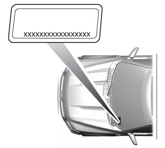
Locating the Vehicle Identification Number
The vehicle identification number is on the left-hand side of the instrument panel.

Copyright © 2026 www.fordescape4.com