Ford Escape 2020-2026 Owners Manual / Capacities and Specifications / Washer Fluid Specification
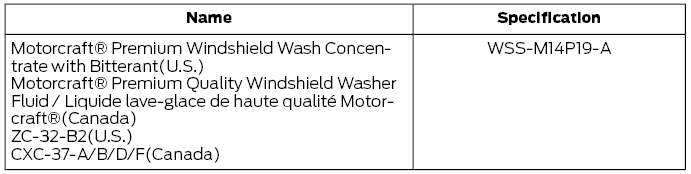
Ford Escape: Capacities and Specifications / Washer Fluid Specification
Capacities

Materials
 Air Conditioning System Capacity and Specification - 2.5L, Hybrid Electric
Vehicle (HEV)/Plug-In Hybrid Electric Vehicle (PHEV)
Air Conditioning System Capacity and Specification - 2.5L, Hybrid Electric
Vehicle (HEV)/Plug-In Hybrid Electric Vehicle (PHEV)
WARNING: The air conditioning
refrigerant system contains refrigerant
under high pressure. Only qualified
personnel should service the air
conditioning refrigerant system...
 Brake Fluid Specification
Use fluid that meets the defined
specification and viscosity grade.
If you do not use fluid that meets the
defined specification and viscosity grade,
it could result in:
Component damage that your vehicle
warranty does not cover...
Other information:
Ford Escape 2020-2026 Service Manual: General Procedures - Air Conditioning (A/C) System Leak Test Using Forming Gas
Special Tool(s) / General Equipment Forming Gas Pressure Gauge and Leak Detector Materials Name Specification Forming Gas - Leak detection All vehicles NOTE: Use a Rotunda-approved Forming Gas A/C System Dealership Leak Detection Service Kit that meets SAE J2790...
Ford Escape 2020-2026 Service Manual: Removal and Installation - Rear Seat Armrest
Special Tool(s) / General Equipment Interior Trim Remover Removal NOTE: Removal steps in this procedure may contain installation details. Remove the rear seat. Refer to: Rear Seat (501-10B Rear Seats, Removal and Installation)...
Categories
- Manuals Home
- 4th Generation Ford Escape Owners Manual
- 4th Generation Ford Escape Service Manual
- Power Outlet - Vehicles With: 12V Power Outlet
- Removal and Installation - All-Wheel Drive (AWD) Module - 1.5L EcoBoost (132kW/180PS) – I3 (Y1)/2.0L EcoBoost (177kW/240PS) – MI4
- Switching the Rear Window Wiper On and Off. Reverse Wipe
- New on site
- Most important about car
Under Hood Fuse Box
Locating the Under Hood Fuse Box

Accessing the Under Hood Fuse Box

Copyright © 2026 www.fordescape4.com