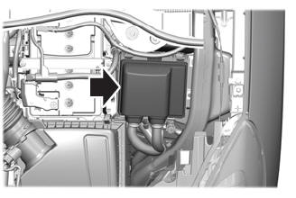
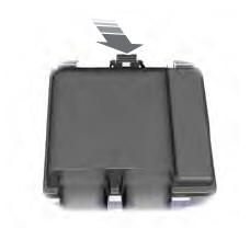
Ford Escape 2020-2024 Service Manual / Powertrain / Engine / Engine Emission Control / Removal and Installation - Differential Pressure Feedback Exhaust Gas Recirculation (EGR) Sensor
Ford Escape: Engine Emission Control / Removal and Installation - Differential Pressure Feedback Exhaust Gas Recirculation (EGR) Sensor
Removal
NOTE: Removal steps in this procedure may contain installation details.
-
NOTE: Do not pull the engine appearance cover forward or sideways to remove. Failure to press straight upward on the underside of the cover at the attachment points may result in damage to the cover or engine components.
-
Remove the engine appearance cover nut.
-
Place your hand under the engine appearance cover at
each grommet location and push straight up to release each grommet from
the studs.
-
After all of the grommets have been released from the studs, remove the appearance cover from the engine.
-
Remove the engine appearance cover nut.
.jpg) |
-
Disconnect the electrical connector.
 |
-
-
Disconnect the differential pressure sensor hoses.
-
Remove the fasteners and remove the differential pressure feedback EGR sensor and hose assembly.
Torque: 89 lb.in (10 Nm)
-
Disconnect the differential pressure sensor hoses.
.jpg) |
Installation
-
To install, reverse the removal procedure.
-
-
If the engine appearance cover stud bolt is loosened
or removed, it must be installed/tightened into the valve cover.
Torque: 106 lb.in (12 Nm)
-
Position the engine appearance cover onto the engine with the grommets aligned with the studs.
-
Press down on the engine appearance cover at each grommet location to attach the grommets onto the studs.
-
Install the engine appearance cover nut.
Torque: 71 lb.in (8 Nm)
-
If the engine appearance cover stud bolt is loosened
or removed, it must be installed/tightened into the valve cover.
.jpg) |
 Removal and Installation - Crankcase Vent Oil Separator
Removal
NOTE:
Removal steps in this procedure may contain installation details.
Refer to: Intake Manifold (303-01B Engine - 2.0L EcoBoost (177kW/240PS) – MI4, Removal and Installation)...
 Removal and Installation - Exhaust Gas Recirculation (EGR) Back Pressure Sensor
Removal
NOTE:
Removal steps in this procedure may contain installation details.
Disconnect the elcetrical connector.
NOTE:
When removing the sensor, use a suitable spanner on
both the sensor body and the sensor mounting boss, to prevent the
removal force from damaging the EGR tube...
Other information:
Ford Escape 2020-2024 Service Manual: General Procedures - Liftgate Alignment
Special Tool(s) / General Equipment Interior Trim Remover Inspection NOTE: Removal steps in this procedure may contain installation details. Inspect the body-to-liftgate door dimensions. Open the liftgate...
Ford Escape 2020-2024 Service Manual: General Procedures - Engine Cooling System Flushing
Flushing WARNING: Always allow the engine to cool before opening the cooling system. Do not unscrew the coolant pressure relief cap when the engine is operating or the cooling system is hot. The cooling system is under pressure; steam and hot liquid can come out forcefully when the cap is loosened slightly...
Categories
- Manuals Home
- 4th Generation Ford Escape Owners Manual
- 4th Generation Ford Escape Service Manual
- Locating the Pre-Collision Assist Sensors
- Plug-In Hybrid Electric Vehicle Drive Modes
- Opening and Closing the Hood
- New on site
- Most important about car
Under Hood Fuse Box
Locating the Under Hood Fuse Box

Accessing the Under Hood Fuse Box

Copyright © 2024 www.fordescape4.com
