Ford Escape: Front Disc Brake / Removal and Installation - Front Brake Flexible Hose
Removal
 WARNING:
Service actions on vehicles equipped with electronic brake
booster and electronic parking brakes may cause unexpected brake
application, which could result in injury to hands or fingers. Put the
brake system into service mode prior to servicing or removing any brake
components. Failure to follow this instruction may result in serious
personal injury.
WARNING:
Service actions on vehicles equipped with electronic brake
booster and electronic parking brakes may cause unexpected brake
application, which could result in injury to hands or fingers. Put the
brake system into service mode prior to servicing or removing any brake
components. Failure to follow this instruction may result in serious
personal injury.
NOTICE: Make sure that all openings are sealed.
NOTICE: Make sure that the brake hose is not twisted and is correctly located.
NOTE: Removal steps in this procedure may contain installation details.
Vehicle with Electric Brake Booster
-
Activate the brake service mode.
Refer to: Brake Service Mode Activation and Deactivation (206-00 Brake System - General Information, General Procedures).
All vehicles
-
Remove the wheel and tire.
Refer to: Wheel and Tire (204-04A Wheels and Tires, Removal and Installation).
-
NOTICE: Make sure that all openings are sealed.
NOTICE: Take extra care not to damage the mating faces.
NOTICE: Make sure that the brake hose is not twisted and is correctly located.
Remove the bolt and disconnect the brake hose. Discard the washers.
Torque: 30 lb.ft (40 Nm)
 |
-
-
NOTICE: Note the routing of the lines and hoses.
Disconnect the brake tube fitting.
Torque: 159 lb.in (18 Nm)
-
NOTE: Make sure a new bolt is installed.
Remove the brake flexible hose bracket bolt.
Torque: 97 lb.in (11 Nm)
-
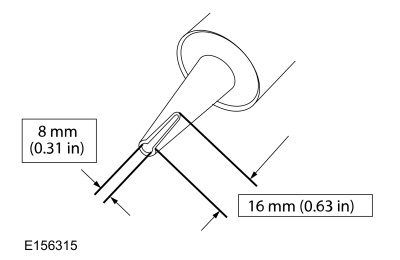
Remove the brake hose clip and the brake flexible hose.
-
 |
Installation
-
To install, reverse the removal procedure.
Vehicle with Electric Brake Booster
-
Deactivate the brake service mode.
Refer to: Brake Service Mode Activation and Deactivation (206-00 Brake System - General Information, General Procedures).
All vehicles
-
Bleed the brake system.
Refer to: Brake System Pressure Bleeding - Vehicles With: Electric Brake Booster (206-00 Brake System - General Information, General Procedures).
Refer to: Brake System Pressure Bleeding - Vehicles With: Vacuum Brake Booster (206-00 Brake System - General Information, General Procedures).


Other information:
Ford Escape 2020-2026 Owners Manual: Second Stage: Checking the tire pressure with the inflator kit
WARNING: If the tire does not inflate to the recommended tire pressure within 15 minutes, stop and call roadside assistance. WARNING: The power plug may get hot after use and should be handled carefully when unplugging. Check the air pressure of your tires as follows: Remove the valve cap from the tire valve. Firmly screw the air compressor hose onto the valve stem by turning clock..
Ford Escape 2020-2026 Owners Manual: Using Seatbelts
WARNING: Depending on where you secure a child restraint, and depending on the child restraint design, you may block access to certain seatbelt buckle assemblies and LATCH lower anchors, rendering those features potentially unusable. To avoid risk of injury, make sure occupants only use seating positions where they are able to be properly restrained. Note: Although the child restraint il..
Categories
- Manuals Home
- 4th Generation Ford Escape Owners Manual
- 4th Generation Ford Escape Service Manual
- Symbols Glossary
- Removal and Installation - All-Wheel Drive (AWD) Module - 1.5L EcoBoost (132kW/180PS) – I3 (Y1)/2.0L EcoBoost (177kW/240PS) – MI4
- Power Outlet - Vehicles With: 12V Power Outlet
- New on site
- Most important about car
Fastening the Seatbelts