Ford Escape: Front Drive Halfshafts / Removal and Installation - Front Halfshaft RH - 2.0L EcoBoost (177kW/240PS) – MI4
Special Tool(s) / General Equipment
 |
204-161
(T97P-1175-A)
Installer, Halfshaft TKIT-1997-LM2 TKIT-1997-F/FM2 TKIT-1997-FLM2 |
 |
205-D070
(D93P-1175-B)
Remover, Front Wheel Hub |
| Tie Rod End Remover | |
Removal
-
Remove the wheel and tire.
Refer to: Wheel and Tire (204-04A Wheels and Tires, Removal and Installation).
-
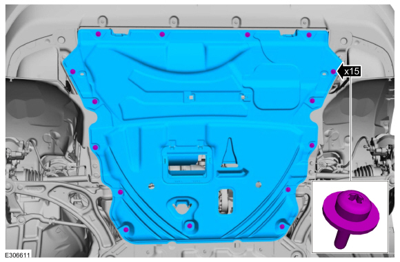
Remove the retainers and the underbody shield.
 |
-
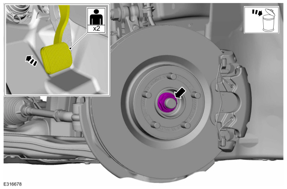
Remove and discard the wheel hub nut.
 |
-
-
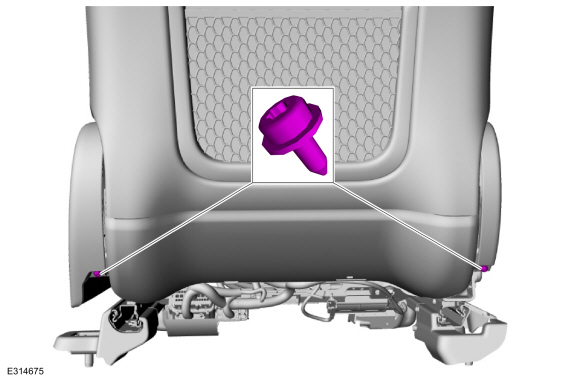
Remove the bolt and position aside the brake hose.
-
Unclip the 2 wire retainers and position aside the wheel speed sensor wiring harness.
-
Remove the bolt and position aside the brake hose.
 |
-
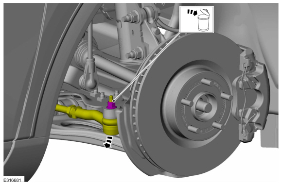
NOTICE: Do not use a hammer to separate the tie rod end from the wheel knuckle or damage to the wheel knuckle may result.
NOTICE: Use care when installing the tie rod separator or damage to the tie rod end boot may occur.
NOTE: Use the hex-holding feature to prevent turning of the stud while removing the tie rod end nut.
Remove and discard the tie rod end nut and separate the tie rod end from the wheel knuckle. Remove the halfshaft.
Use the General Equipment: Tie Rod End Remover
 |
-
NOTICE: Do not use a prying device to open the slot in the knuckle to separate the lower ball joint from the knuckle assembly. Damage to the knuckle assembly may occur.
NOTICE: Do not use a prying device or separator fork between the ball joint and the wheel knuckle. Damage to the ball joint or ball joint seal may result. Only use the pry bar by inserting it into the lower arm body opening.
NOTICE: Use care when releasing the lower arm and wheel knuckle into the resting position or damage to the ball joint seal may occur.
NOTICE: Do not use power tools to remove or install the lower arm outboard nut. Damage to the ball joint or ball joint seal may occur.
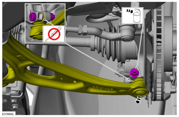
NOTE: Use the TORX PLUS® holding feature to prevent the ball stud from turning while removing or installing the lower arm outboard nut. Torx® and TORX PLUS® is a reg. tm of Acument Intellectual Properties, LLC.
Remove and discard the ball joint pinch bolt and nut and separate the lower arm from the wheel knuckle.
 |
-
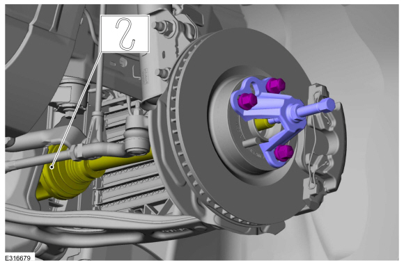
NOTICE: Do not bend the inner joint more than 18 degrees and the outer joint more than 45 degrees. Damage to the shaft will occur.
Using the special tool, press the halfshaft from the wheel bearing and hub. Support the halfshaft in a level position.
Use Special Service Tool: 205-D070 (D93P-1175-B) Remover, Front Wheel Hub.
 |
-
Remove and discard the halfshaft retaining strap and nuts.
 |
-
Remove the halfshaft.
 |
Installation
-
Clean and inspect the inboard end of the halfshaft.
 |
-
Clean and inspect the outer CV housing.
 |
-
Install a new halfshaft seal.
Refer to: Halfshaft Seal RH - FWD (307-01B Automatic Transmission - Automatic Transmission – HF45, Removal and Installation).
Refer to: Halfshaft Seal RH - FWD (307-01B Automatic Transmission - Automatic Transmission – HF45, Removal and Installation).
-
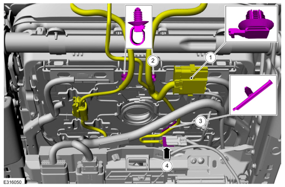
Insert the intermediate shaft until the intermediate
shaft bearing is centered in the concave groove of the intermediate
shaft bearing bracket.
 |
-
Install the new halfshaft retaining strap and nuts.
Torque:
Stage 1: Tighten lower nut to: 44 lb.in (5 Nm)
Stage 2: Tighten upper nut to: 18 lb.ft (25 Nm)
Stage 3: Tighten lower nut to: 18 lb.ft (25 Nm)
 |
-
NOTE: Do not install the halfshaft any deeper than the centerline of the bearing with the centerline of the bracket. Over-installation of the halfshaft and pulling the halfshaft back out to align the bearing in the bracket could damage the intermediate shaft seal.
-
Insert halfshaft through the wheel bearing.
-
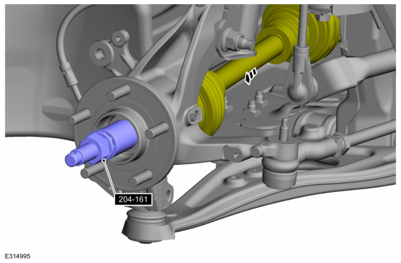
Using the special tool, seat the halfshaft splines in the wheel bearing.
Use Special Service Tool: 204-161 (T97P-1175-A) Installer, Halfshaft.
-
Insert halfshaft through the wheel bearing.
 |
-
NOTICE: Do not use power tools to remove or install the lower arm outboard nut. Damage to the ball joint or ball joint seal may occur.
NOTE: Use the TORX PLUS® holding feature to prevent the ball stud from turning while removing or installing the lower arm outboard nut. Torx® and TORX PLUS® is a reg. tm of Acument Intellectual Properties, LLC.
Position the ball joint into the wheel knuckle and install the new ball joint pinch bolt and nut.
Torque: 81 lb.ft (110 Nm)
 |
-
NOTICE: Use care when installing the tie rod separator or damage to the tie rod end boot may occur.
NOTE: Use the hex-holding feature to prevent turning of the stud while installing the tie rod end nut.
Attach the tie rod end to the wheel knuckle and install the new tie rod end nut.
Torque: 35 lb.ft (48 Nm)
 |
-
-
Position the brake hose and install the bolt.
Torque: 97 lb.in (11 Nm)
-
Position the wheel speed sensor wiring harness and clip the 2 wire retainers.
-
Position the brake hose and install the bolt.
|
-
NOTICE: Do not tighten the front wheel hub nut with the vehicle on the ground. The nut must be tightened to specification before the vehicle is lowered onto the wheels. Wheel bearing damage will occur if the wheel bearing is loaded with the weight of the vehicle applied.
NOTICE: Install and tighten the new wheel hub nut to specification in a continuous rotation. Always install a new wheel hub nut after loosening or when not tightened to specification in a continuous rotation or damage to the components may occur.
NOTE: Apply the brake to keep the halfshaft from rotating.
While an assistant applies the brake, install the new wheel hub nut.
Torque:
Stage 1: 74 lb.ft (100 Nm)
Stage 2: 60°
 |
-
Check the transmission fluid level.
Refer to: Transmission Fluid Level Check (307-01A Automatic Transmission - 8-Speed Automatic Transmission – 8F35/8F40, General Procedures).
Refer to: Transmission Fluid Level Check (307-01B Automatic Transmission - Automatic Transmission – HF45, General Procedures).
Refer to: Transmission Fluid Level Check (307-01B Automatic Transmission - Automatic Transmission – HF45, General Procedures).
-
Install the underbody shield and tighten the retainers.
Torque: 13 lb.in (1.5 Nm)
|
-
Install the wheel and tire.
Refer to: Wheel and Tire (204-04A Wheels and Tires, Removal and Installation).
 Removal and Installation - Front Halfshaft RH - 1.5L EcoBoost (132kW/180PS) – I3 (Y1)
Special Tool(s) /
General Equipment
204-161
(T97P-1175-A)
Installer, HalfshaftTKIT-1997-LM2TKIT-1997-F/FM2TKIT-1997-FLM2
205-D070
(D93P-1175-B)
Remover, Front Wheel Hub
Tie Rod End Remover
Removal
Remove the wheel and tire...
 Removal and Installation - Front Halfshaft RH - 2.5L Duratec – Hybrid (121kW/164PS) (BG)
Special Tool(s) /
General Equipment
204-161
(T97P-1175-A)
Installer, HalfshaftTKIT-1997-LM2TKIT-1997-F/FM2TKIT-1997-FLM2
205-D070
(D93P-1175-B)
Remover, Front Wheel Hub
Tie Rod End Remover
Removal
Remove the wheel and tire...
Other information:
Ford Escape 2020-2025 Service Manual: Diagnosis and Testing - Charging System - 1.5L EcoBoost (132kW/180PS) – I3 (Y1)
Inspection and Verification Verify the customer concern by operating the charging system. Before diagnosing or repairing the charging system inspect the following items: Check the battery for loose, damaged or corroded connections...
Ford Escape 2020-2025 Service Manual: Removal and Installation - Timing Chain
Removal NOTE: During engine repair procedures, cleanliness is extremely important. Any foreign material, including any material created while cleaning gasket surfaces, that enters the oil passages, coolant passages or the oil pan can cause engine failure...
Categories
- Manuals Home
- 4th Generation Ford Escape Owners Manual
- 4th Generation Ford Escape Service Manual
- Adjusting the Headlamps
- Switching the Lane Keeping System On and Off. Switching the Lane Keeping System Mode. Alert Mode
- All-Wheel Drive
- New on site
- Most important about car
Vehicle Identification
Locating the Vehicle Identification Number
The vehicle identification number is on the left-hand side of the instrument panel.
