Ford Escape: Handles, Locks, Latches and Entry Systems / Removal and Installation - Rear Door Latch
Removal
NOTE: LH (left-hand) side shown, RH (right-hand) side similar.
-
Remove the rear door window regulator and motor.
Refer to: Rear Door Window Regulator and Motor (501-11 Glass, Frames and Mechanisms, Removal and Installation).
-
Remove the exterior rear door handle.
Refer to: Exterior Rear Door Handle (501-14 Handles, Locks, Latches and Entry Systems, Removal and Installation).
-
Remove the screw from the exterior rear door handle reinforcement.
Torque: 19 lb.in (2.2 Nm)
.jpg) |
-
Remove the rear door latch bolts.
Torque: 17 lb.in (1.9 Nm)
 |
-
Remove the rear door latch bolts.
Torque: 71 lb.in (8 Nm)
.jpg) |
-
Remove the rear door latch.
-
Disconnect the wiring harness routing clips and
position the exterior rear door handle reinforcement wiring harness
aside.
-
Disconnect the rear door latch electrical connector.
-
Route the interior rear door handle cable through the inner door.
-
Remove the rear door latch.
-
Disconnect the wiring harness routing clips and
position the exterior rear door handle reinforcement wiring harness
aside.
.jpg) |
-
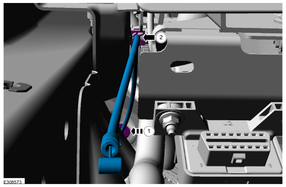
NOTE: This step is only necessary when installing a new component.
NOTE: Follow the unique instructions or graphic for this step in installation.
Release the cable tension by turning the release screw until the handle lever releases from the stop.
-
Turn the release screw until the handle lever releases from the stop.
-
Release the handle lever from the stop.
-
Turn the release screw until the handle lever releases from the stop.
.jpg) |
-
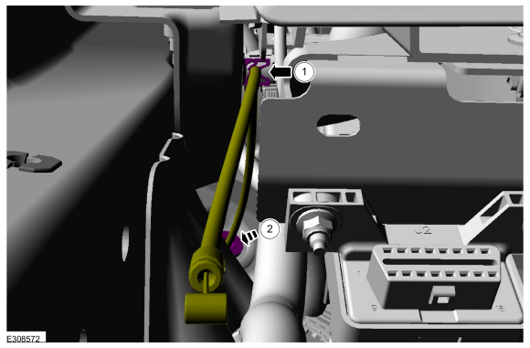
NOTE: This step is only necessary when installing a new component.
Remove the exterior rear door handle reinforcement.
-
Detach the cable from the exterior rear door handle reinforcement.
-
Remove the cable eyelet from the lever.
-
Press the locking tab down
-
Slide the exterior front door handle reinforcement forward.
-
Remove the exterior front door handle reinforcement.
-
Detach the cable from the exterior rear door handle reinforcement.
.jpg) |
-
NOTE: This step is only necessary when installing a new component.
Remove the rear door glass run and bracket.
-
Release the top retaining tab on the rear door glass run and bracket.
-
Release the bottom retaining tab on the rear door glass run and bracket.
-
Remove the rear door glass run and bracket.
-
Release the top retaining tab on the rear door glass run and bracket.
.jpg) |
-
NOTE: This step is only necessary when installing a new component.
Remove the exterior rear door handle reinforcement to rear door latch cable access cover.
.jpg) |
-
NOTE: This step is only necessary when installing a new component.
Remove the exterior rear door handle reinforcement to rear door latch cable.
.jpg) |
-
NOTE: This step is only necessary when installing a new component.
Remove the interior rear door handle cable and lock indicator cable access covers.
-
Remove the lock indicator cable access cover.
-
Remove the interior rear door handle cable access cover.
-
Remove the lock indicator cable access cover.
.jpg) |
-
NOTE: This step is only necessary when installing a new component.
Remove the interior rear door handle cable and lock indicator cable.
-
Remove the lock indicator cable.
-
Remove the interior rear door handle cable.
-
Remove the lock indicator cable.
.jpg) |
Installation
-
To install, reverse the removal procedure.
-
NOTE: This step is only necessary when installing a new component.
NOTE: This step must be done correctly or the exterior door handle will not engage the lever on installation.
Position the exterior rear door handle reinforcement in the service position.
-
While keeping tension on the cable and holding the handle lever in the engaged position against the stop.
-
Turn the release screw until the handle lever is positioned against the stop.
-
While keeping tension on the cable and holding the handle lever in the engaged position against the stop.
 |
-
If the door is equipped with one touch up/down, carry out the power
door window initialization.
Refer to: Power Door Window Initialization - Vehicles With: One-Touch
Open and Close Front Windows (501-11 Glass, Frames and Mechanisms,
General Procedures).
 Removal and Installation - Liftgate Release Switch
Removal
Remove the liftgate trim panel.
Refer to: Liftgate Trim Panel (501-05 Interior Trim and Ornamentation, Removal and Installation).
Remove the liftgate release switch...

Other information:
Ford Escape 2020-2026 Service Manual: Removal and Installation - Cowl Panel Grille
Removal NOTE: Removal steps in this procedure may contain installation details. Remove the windshield wiper pivot arm. Refer to: Windshield Wiper Pivot Arm (501-16 Wipers and Washers, Removal and Installation). Remove the clips. Pull outward to release the locking clips and position the upper portion of the cowl panel grille away fro..
Ford Escape 2020-2026 Service Manual: General Procedures - Roof Opening Panel Alignment
Adjustment Measurement Measure the roof opening panel movable glass height/flushness. Measure the roof opening panel sliding glass front edge-to-header panel height/flushness. Refer to the specifications as shown. Measure the roof opening panel sliding glass rear edge-to-roof opening panel fixed glass height/flushness. Refer to the specifications as shown. ..
Categories
- Manuals Home
- 4th Generation Ford Escape Owners Manual
- 4th Generation Ford Escape Service Manual
- Locating the Pre-Collision Assist Sensors
- Rear View Camera
- Child Safety Locks
- New on site
- Most important about car
Push Button Ignition Switch

Switching the Ignition Off
When the ignition is on or in accessory mode, press the push button ignition switch once without your foot on the brake pedal.