Ford Escape 2020-2026 Service Manual / Chassis / Steering System / Steering Column / Removal and Installation - Steering Wheel
Ford Escape: Steering Column / Removal and Installation - Steering Wheel
Special Tool(s) / General Equipment
| Adhesive Tape |
Removal
NOTICE: To prevent damage to the clockspring, make sure the front wheels are in the straight-ahead position.
NOTE: Removal steps in this procedure may contain installation details.
-
Remove the driver airbag.
Refer to: Driver Airbag (501-20B Supplemental Restraint System, Removal and Installation).
-
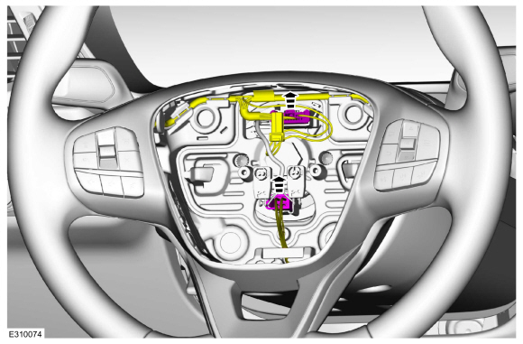
Disconnect the steering wheel electrical connectors.
 |
-
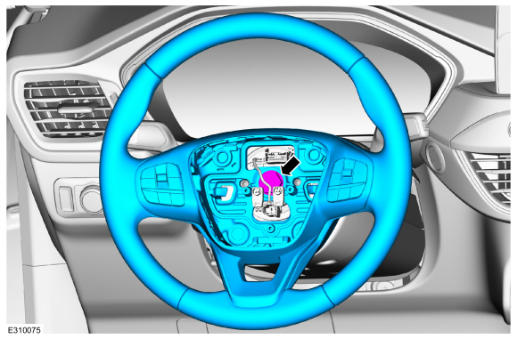
Remove the steering wheel retainer and the steering wheel.
Torque: 35 lb.ft (48 Nm)
 |
-
NOTE: Make sure the clockspring rotor does not rotate.
NOTE: Make sure the clockspring pins are not bent or damaged.
Tape the clockspring rotor to the outer housing to keep it from rotating.
Use the General Equipment: Adhesive Tape
 |
-
NOTE: This step is only necessary when installing a new component.
Remove the steering wheel multifunction switch.
Refer to: Steering Wheel Multifunction Switch (211-05 Steering Wheel and Column Electrical Components, Removal and Installation).
Installation
-
To install, reverse the removal procedure.
 Removal and Installation - Steering Column
Removal
NOTICE:
To prevent damage to the clockspring, make sure the front wheels are in the straight-ahead position.
NOTICE:
Precise tolerances are required when manufacturing a
steering column...

Other information:
Ford Escape 2020-2026 Service Manual: General Procedures - Corrosion Prevention
Special Tool(s) / General Equipment Rust Protection Coating Gun Undercoating Gun Materials Name Specification ValuGard™ Premium UndercoatingVG101, VG101A - ValuGard™ Rust InhibitorVG104, VG104A - Motorcraft® Metal Surface Prep WipesZC-31-B - Repair NOTE: Undercoating NOTE: The following illustrations are not vehicle spe..
Ford Escape 2020-2026 Service Manual: Removal and Installation - Rear Gate Trunk Module (RGTM)
Removal NOTE: Removal steps in this procedure may contain installation details. NOTE: This step is only necessary when installing a new component. The PMI process must begin with the current RGTM installed. If the current RGTM does not respond to the diagnostic scan tool, the tool may prompt for As-Built Data as part of the repair. Using a diagnostic scan tool, begin the PMI ..
Categories
- Manuals Home
- 4th Generation Ford Escape Owners Manual
- 4th Generation Ford Escape Service Manual
- Electric Parking Brake
- Power Outlet - Vehicles With: 12V Power Outlet
- Accessing the Trip Computer. Resetting the Trip Computer
- New on site
- Most important about car
Symbols Glossary
These are some of the symbols you may see on your vehicle.
 Air conditioning system
Copyright © 2026 www.fordescape4.com