Ford Escape: Steering Column / Removal and Installation - Steering Column
Removal
NOTICE: To prevent damage to the clockspring, make sure the front wheels are in the straight-ahead position.
NOTICE: Precise tolerances are required when manufacturing a steering column. Never install a repaired, rebuilt, aftermarket, or remanufactured steering column. Always install a new steering column. Failure to follow this direction can result in steering column failure.
NOTE: Removal steps in this procedure may contain installation details.
-
NOTE: This step is only necessary when installing a new component.
If installing a new steering column, connect the scan tool and upload the module configuration information from the PSCM .
Refer to: Module Configuration - System Operation and Component Description (418-01 Module Configuration, Description and Operation).
-
Depower the SRS .
Refer to: Supplemental Restraint System (SRS) Depowering (501-20B Supplemental Restraint System, General Procedures).
-
NOTE: This step is only necessary when installing a new component.
Remove the SCCM .
Refer to: Steering Column Control Module (SCCM) (211-05 Steering Wheel and Column Electrical Components, Removal and Installation).
-
NOTE: This step is not necessary when installing a new component.
Remove the steering column shrouds.
Refer to: Steering Column Shrouds (501-05 Interior Trim and Ornamentation, Removal and Installation).
-
NOTICE: Do not allow the steering wheel to rotate while the steering column shaft is disconnected or damage to the clockspring may result. If there is evidence that the shaft has rotated, remove and recenter the clockspring.
Secure the steering wheel.
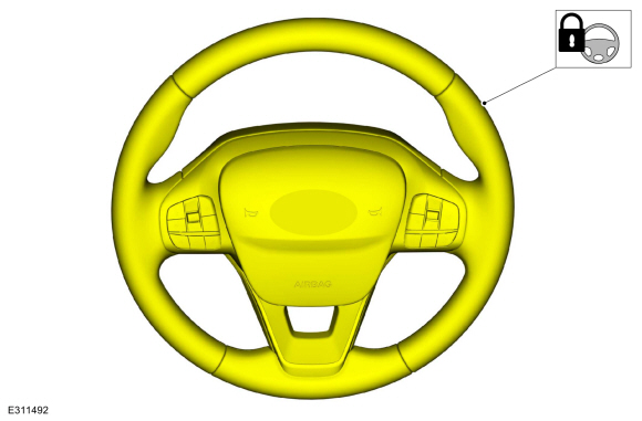 |
-
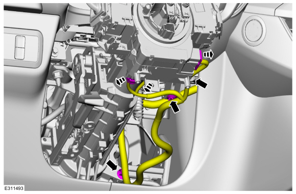
Disconnect the steering column electrical connectors and position the harness aside.
 |
-
-
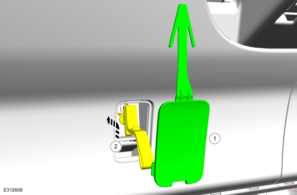
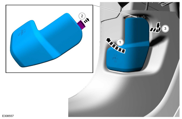
Remove the manual park release cover.
-
Push the manual park release up and through the steering column opening trim panel.
-
Remove the manual park release cover.
 |
-
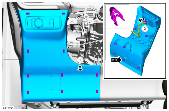
Remove the steering column opening trim panel.
-
Remove the steering column opening trim panel.
-
Disconnect the headlamp switch electrical connector.
-
Remove the steering column opening trim panel.
 |
-
 WARNING:
Do not reuse steering column shaft bolts. This may
result in fastener failure and steering column shaft detachment or loss
of steering control. Failure to follow this instruction may result in
serious injury to vehicle occupant(s).
WARNING:
Do not reuse steering column shaft bolts. This may
result in fastener failure and steering column shaft detachment or loss
of steering control. Failure to follow this instruction may result in
serious injury to vehicle occupant(s).
-
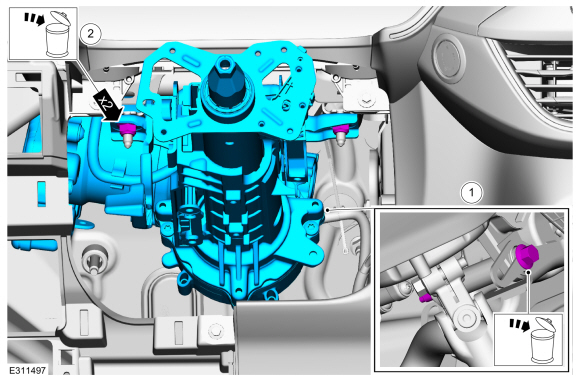
Remove and discard the steering shaft coupler retainer.
Torque: 46 lb.ft (63 Nm)
-
Separate the steering column shaft from the steering gear.
-
Remove and discard the steering shaft coupler retainer.
 |
-
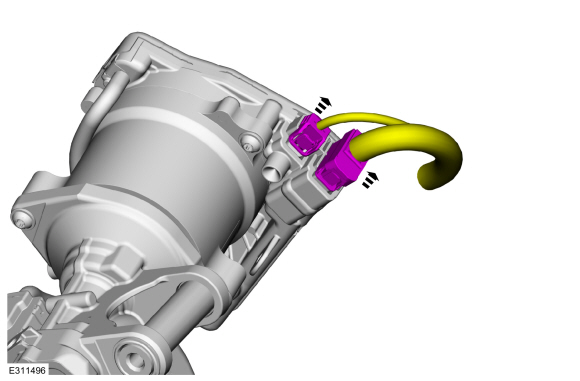
Disconnect the steering column EPAS electrical connectors.
 |
-
WARNING:
Do not reuse steering column nuts. This may result
in fastener failure and steering column detachment or loss of steering
control. Failure to follow this instruction may result in serious injury
to vehicle occupant(s).
Remove the steering column.
-
Remove and discard the steering column mounting bolt.
-
Remove and discard the nuts and remove the steering column.
-
Transfer parts as required.
-
Remove and discard the steering column mounting bolt.
 |
-
WARNING:
Do not reuse steering column shaft bolts. This may
result in fastener failure and steering column shaft detachment or loss
of steering control. Failure to follow this instruction may result in
serious injury to vehicle occupant(s).
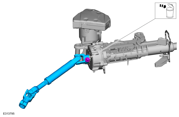
NOTE: This step is only necessary when installing a new component.
Remove and discard the steering shaft coupler retainer and remove the steering column intermediate shaft.
Torque:
Stage 1: 35 lb.ft (48 Nm)
Stage 2: 120°
 |
Installation
-
To install, reverse the removal procedure.
-
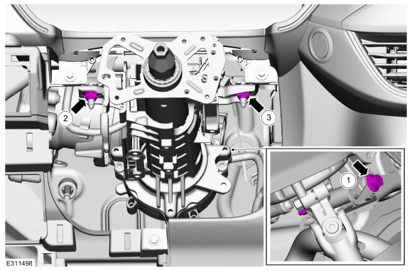
Tighten the fasteners following the sequence shown.
Torque:
1: 18 lb.ft (25 Nm)
2: 18 lb.ft (25 Nm)
3: 18 lb.ft (25 Nm)
 |
-
Repower the SRS .
Refer to: Supplemental Restraint System (SRS) Repowering (501-20B Supplemental Restraint System, General Procedures).
-
NOTE: This step is only necessary when installing a new component.
If a new steering column was installed, download the PSCM configuration from the scan tool to the new PSCM .
Refer to: Module Configuration - System Operation and Component Description (418-01 Module Configuration, Description and Operation).
-
NOTE: This step is only necessary when installing a new component.
To relearn steering angles, drive the vehicle above 64km/h (40 mph) for a minimum of 1 mile while maintaining the steering wheel in a straight ahead position with minimal steering input for at least 30 seconds.

 Removal and Installation - Steering Wheel
Special Tool(s) /
General Equipment
Adhesive Tape
Removal
NOTICE:
To prevent damage to the clockspring, make sure the front wheels are in the straight-ahead position...
Other information:
Ford Escape 2020-2026 Service Manual: General Procedures - Evaporator Core Leak Check
Inspection Recover the refrigerant. Refer to: Air Conditioning (A/C) System Recovery, Evacuation and Charging (412-00 Climate Control System - General Information, General Procedures). Disconnect the evaporator from the A/C system...
Ford Escape 2020-2026 Service Manual: Description and Operation - Communications Network - Overview
Overview Multiplexing is a method of sending 2 or more signals simultaneously over a single circuit. Multiplexing allows 2 or more electronic modules (nodes) to communicate over a twisted wire pair [data (+) and data (-)] network. The information or messages that can be communicated on these wires consists of commands, status or data...
Categories
- Manuals Home
- 4th Generation Ford Escape Owners Manual
- 4th Generation Ford Escape Service Manual
- Drive Modes
- General Procedures - Transmission Fluid Level Check
- Symbols Glossary
- New on site
- Most important about car
Fastening the Seatbelts
