Ford Escape: Automatic Transmission - Automatic Transmission – HF45 / Removal and Installation - Transmission Support Insulator
Special Tool(s) /
General Equipment
| Trolley Jack |
| Wooden Block |
Removal
-
Drain the Electric Powertrain Cooling System.
Refer to: Cooling System Filling and Bleeding (303-03D Electric
Powertrain Cooling - Hybrid Electric Vehicle (HEV), General Procedures).
-
Disable the vehicle high-voltage electrical system.
Refer to: High Voltage System De-energizing (414-03A High Voltage Battery, Mounting and Cables, General Procedures).
-
Remove the air cleaner outlet pipe.
Refer to: Air Cleaner Outlet Pipe (303-12C Intake Air Distribution and Filtering, Removal and Installation).
-
Remove the air cleaner.
Refer to: Air Cleaner (303-12C Intake Air Distribution and Filtering, Removal and Installation).
-
NOTE:
Be prepared to catch a minimal amount of escaping coolant fluid.
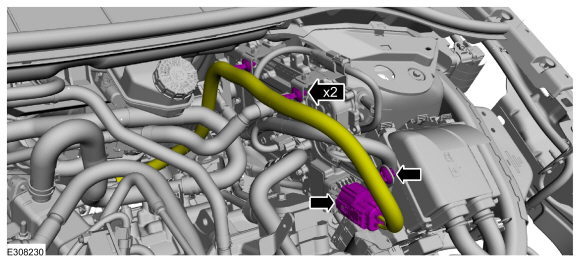
Disconnect the coolant hoses.
-
Disconnect the electrical connector and wiring harness retainers.
-
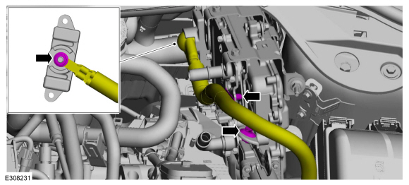
Disconnect the electrical connectors and wiring harness retainers.
-
Disconnect the electrical connector.
-
Remove wiring harness nut and disconnect the wiring harness retainers.
-
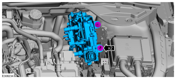
NOTICE:
Place tape over the connectors on the ISC to prevent contaminating the connector pins.
Disconnect the ISC (Inverter System Controller) electrical connectors.
-
NOTICE:
Place absorbent towels under the coolant connections to prevent coolant from contacting the ISC.
Disconnect the coolant hose.
-
Remove the bolts and position aside the coolant tube.
-
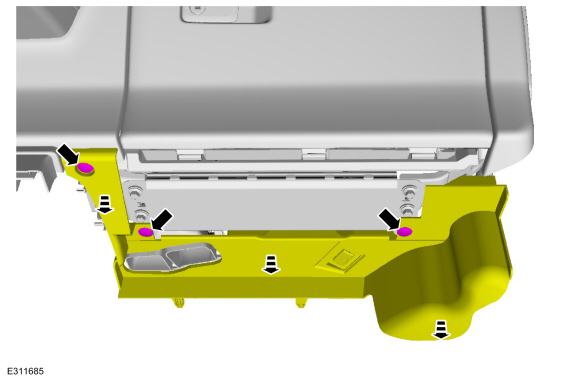
Remove the bolts and the power converter.
-
Position the jack and wooden block under the transmission case outer edge to support the transmission.
Use the General Equipment: Trolley Jack
Use the General Equipment: Wooden Block
-
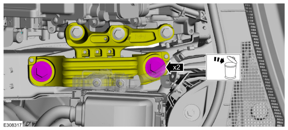
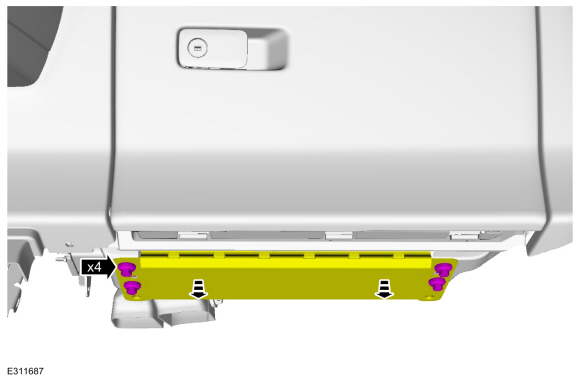
Remove and discard the transmission support insulator bolts.
-
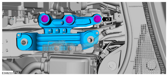
Remove the transmission support insulator bolts. Remove the transmission support insulator.
Installation
-
Install the transmission support insulator and bolts finger tight.
-
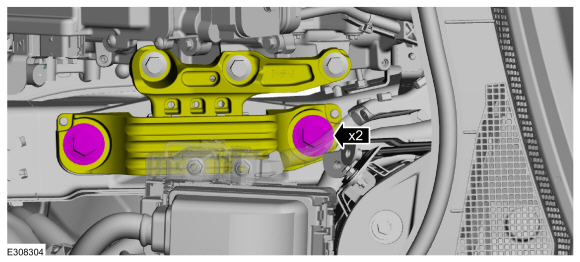
Install new transmission support insulator bolts.
Torque:
184 lb.ft (250 Nm)
-
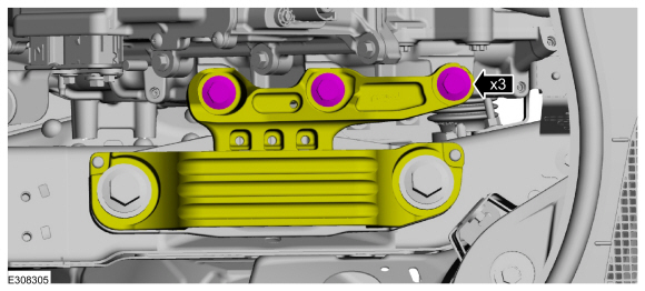
Tighten the transmission support insulator bolts.
Torque:
92 lb.ft (125 Nm)
-
Install the power converter and the bolts.
Torque:
159 lb.in (18 Nm)
-
NOTICE:
Be careful not to get residual coolant in the open ISC connectors.
Position back the coolant tube and install the bolts.
Torque:
71 lb.in (8 Nm)
-
NOTE:
When connecting the coolant tube, push-click-pull on the coolant tube to ensure proper connection.
Connect the coolant hose.
-
-
Connect C199A (40 pin connector) and engage the lever lock.
-
Connect C199B (22 pin connector).
-
Connect the converter wiring harness retainers and install the wiring harness nut.
Torque:
53 lb.in (6 Nm)
-
Connect the electrical connector.
-
Connect the electrical connectors and wiring harness retainers.
-
Connect the electrical connector and wiring harness retainers.
-
Connect the coolant hoses.
-
Install the air cleaner outlet pipe.
Refer to: Air Cleaner Outlet Pipe (303-12C Intake Air Distribution and Filtering, Removal and Installation).
-
Install the air cleaner.
Refer to: Air Cleaner (303-12C Intake Air Distribution and Filtering, Removal and Installation).
-
Connect the vehicle high-voltage electrical system.
Refer to: High Voltage System De-energizing (414-03A High Voltage Battery, Mounting and Cables, General Procedures).
-
Fill and bleed the Electric Powertrain Cooling System.
Refer to: Cooling System Filling and Bleeding (303-03D Electric
Powertrain Cooling - Hybrid Electric Vehicle (HEV), General Procedures).
Materials
Name
Specification
Motorcraft® MERCON® ULV Automatic Transmission FluidXT-12-QULV
WSS-M2C949-A, MERCON® ULV
Removal
With the vehicle in NEUTRAL, position it on a hoist...
NOTE:
The transmission cannot be removed from the vehicle separate
from the engine. Separate the transmission from the engine following the
additional steps in the transmission procedure...
Other information:
Deactivation
NOTE:
During vehicle build, some modules, such as the IPC and BCM module are set in factory mode.
Factory mode reduces the drain on the battery during longer periods
where the vehicle is not used. While in the factory mode, various
systems may be altered or disabled and the IPC
displays FACTORY MODE CONTACT DEALER in the message center...
INSTALLING AND REMOVING THE LUGGAGE COMPARTMENT COVER
WARNING: Make sure that you
properly secure the luggage cover.
Failure to follow this instruction could
result in personal injury in the event of a
sudden stop or crash.
WARNING: Do not place objects
on the luggage cover...
.jpg)
.jpg)
.jpg)
.jpg)
.jpg)
.jpg)
.jpg)
 Removal and Installation - Transmission Fluid Auxiliary Pump
 Removal - Transmission