Ford Escape 2020-2026 Service Manual / Body and Paint / Body and Paint / Front End Body Panels / Removal and Installation - Fender
Ford Escape: Front End Body Panels / Removal and Installation - Fender
Removal
NOTE: Removal steps in this procedure may contain installation details.
-
Remove the cowl panel grille.
Refer to: Cowl Panel Grille (501-02 Front End Body Panels, Removal and Installation).
-
Remove the front fender splash shield.
Refer to: Fender Splash Shield (501-02 Front End Body Panels, Removal and Installation).
-
Remove the headlamp assembly.
Refer to: Headlamp Assembly (417-01 Exterior Lighting, Removal and Installation).
-
Remove the bolts.
Torque: 80 lb.in (9 Nm)
 |
-
Remove the front door.
Refer to: Front Door (501-03 Body Closures, Removal and Installation).
-
Remove the bolt.
Torque: 80 lb.in (9 Nm)
.jpg) |
-
Remove the fender baffle.
.jpg) |
-
Remove the bolt.
Torque: 80 lb.in (9 Nm)
.jpg) |
-
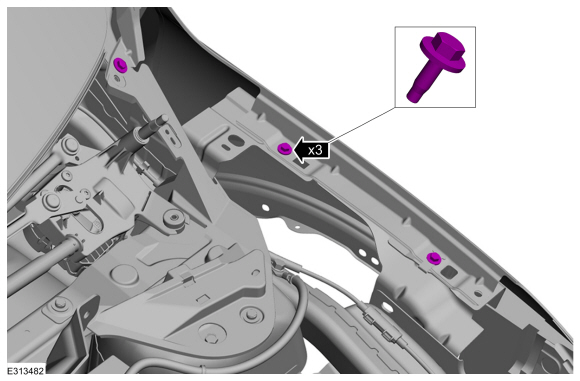
Remove the bolts.
Torque: 80 lb.in (9 Nm)
.jpg) |
-
Remove the bolts.
Torque: 80 lb.in (9 Nm)
.jpg) |
-
Remove the fender.
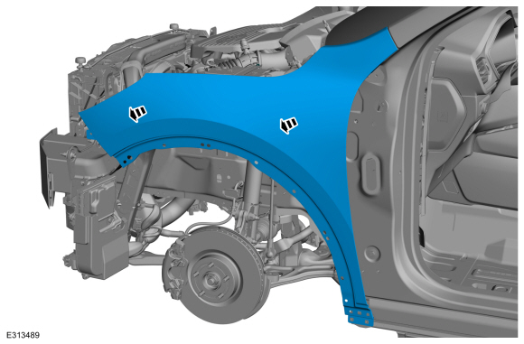 |
-
NOTE: This step is only necessary when installing a new component.
If equipped
Remove the fender insulation.
.jpg) |
Installation
-
To install, reverse the removal procedure.
 Removal and Installation - Engine Front Undershield
Removal
NOTE:
Removal steps in this procedure may contain installation details.
With the vehicle in NEUTRAL, position it on a hoist.
Refer to: Jacking and Lifting (100-02 Jacking and Lifting)
...
 Removal and Installation - Fender - Plug-In Hybrid Electric Vehicle (PHEV)
Removal
NOTE:
Removal steps in this procedure may contain installation details.
Remove the cowl panel grille.
Refer to: Cowl Panel Grille (501-02 Front End Body Panels, Removal and Installation)...
Other information:
Ford Escape 2020-2026 Service Manual: Removal and Installation - Coolant Pump
Special Tool(s) / General Equipment Hose Clamp Remover/Installer Removal Drain the cooling system. Refer to: Engine Cooling System Draining, Vacuum Filling and Bleeding (303-03C Engine Cooling, General Procedures). Disconnect the electrical connector...
Ford Escape 2020-2026 Service Manual: Description and Operation - Horn - System Operation and Component Description
System Operation System Diagram E341593 *.sttxt { visibility: hidden; } *.stcallout { visibility: visible; } 1 Horns 2 Horn Switch 3 BCM-C 4 BCM 5 SCCM 6 Clockspring Item Description 1 Horns 2 Horn Switch 3 BCM-C 4 BCM 5 SCCM 6 Clockspring Horn Opera..
Categories
- Manuals Home
- 4th Generation Ford Escape Owners Manual
- 4th Generation Ford Escape Service Manual
- All-Wheel Drive
- General Procedures - Transmission Fluid Level Check
- Switching the Lane Keeping System On and Off. Switching the Lane Keeping System Mode. Alert Mode
- New on site
- Most important about car
Under Hood Fuse Box
Locating the Under Hood Fuse Box

Accessing the Under Hood Fuse Box

Copyright © 2026 www.fordescape4.com