Ford Escape 2020-2026 Service Manual / Chassis / Driveline / Front Drive Halfshafts / Removal and Installation - Intermediate Shaft
Ford Escape: Front Drive Halfshafts / Removal and Installation - Intermediate Shaft
Materials
| Name | Specification |
|---|---|
| Motorcraft® MERCON® ULV Automatic Transmission Fluid XT-12-QULV |
WSS-M2C949-A, MERCON® ULV |
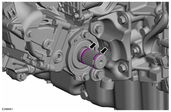
Removal
-
Remove the front halfshaft RH .
-
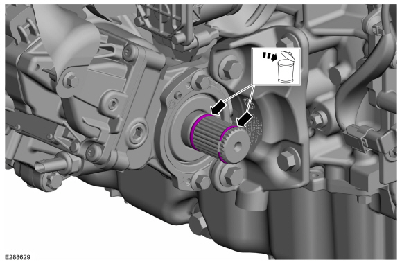
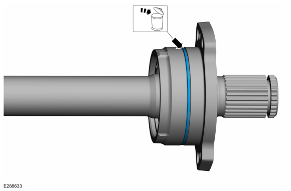
Remove and discard the circlip and O-ring seal from the intermediate shaft.
 |
-
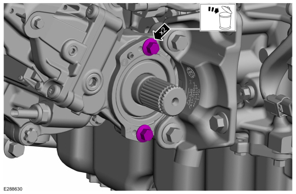
Remove and discard the intermediate shaft mounting bolts.
 |
-
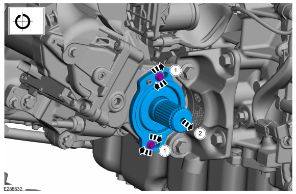
Install two 6mm x 1.0 x 20mm bolts into the flange threads.
 |
-
Turn bolts evenly one turn at a time and remove the intermediate shaft.
 |
-
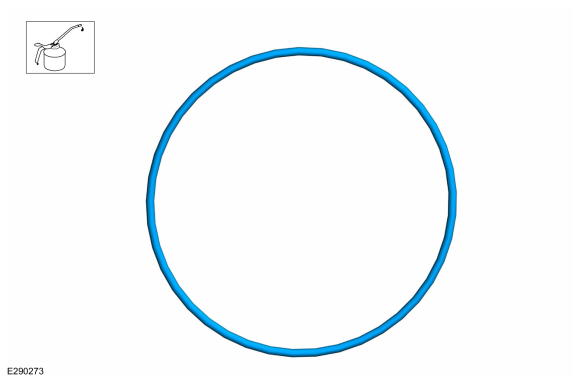
Remove and discard the intermediate shaft bearing O-ring seal.
 |
Installation
-
NOTE: Component(s) must be lubricated with clean automatic transmission fluid.
Lubricate the new intermediate shaft bearing O-ring seal before installation with the specified material.
- Material: Motorcraft® MERCON® ULV Automatic Transmission Fluid / XT-12-QULV (WSS-M2C949-A, ) (MERCON® ULV)
 |
-
Install the new intermediate shaft bearing O-ring seal.
 |
-
-
Install the intermediate shaft in the PTU until the shaft flange is flush with the PTU housing.
-
NOTE: Don't tap on the flange ears.
-
NOTE: If necessary, tap on the bearing housing around the seal flange.
-
Install the intermediate shaft in the PTU until the shaft flange is flush with the PTU housing.
 |
-
NOTE: Make sure that new bolts are installed.
Install new bolts.
Torque: 18 lb.ft (25 Nm)
 |
-
Install the new circlip and O-ring seal on the intermediate shaft.
 |
-
Install the front halfshaft RH .
-
Check the transmission fluid level.
Refer to: Transmission Fluid Level Check (307-01A Automatic Transmission - 8-Speed Automatic Transmission – 8F35/8F40, General Procedures).
Refer to: Transmission Fluid Level Check (307-01A Automatic Transmission - 8-Speed Automatic Transmission – 8F35/8F40, General Procedures).
Refer to: Transmission Fluid Level Check (307-01A Automatic Transmission - 8-Speed Automatic Transmission – 8F35/8F40, General Procedures).
 Removal and Installation - Front Halfshaft RH
Special Tool(s) /
General Equipment
204-161
(T97P-1175-A)
Installer, HalfshaftTKIT-1997-LM2TKIT-1997-F/FM2TKIT-1997-FLM2
205-D070
(D93P-1175-B)
Remover, Front Wheel Hub
Tie Rod End Remover
Removal
Remove the wheel and tire...

Other information:
Ford Escape 2020-2026 Owners Manual: Storing Your Vehicle
Preparing Your Vehicle for Storage If you plan on storing your vehicle for 30 days or more, the following maintenance recommendations ensures your vehicle stays in good operating condition. Under various conditions, long-term storage may lead to degraded engine performance or failure unless you use specific precautions to preserve your vehicle. General Store all vehicles in a dry, ventila..
Ford Escape 2020-2026 Service Manual: General Procedures - Air Conditioning (A/C) Clutch Air Gap Adjustment
Activation NOTE: Compressor with a spring rubber clutch shown others similar. Check the A/C clutch air gap at 3 equally spaced places between the clutch plate and the A/C clutch pulley. Refer to: Specifications (412-00 Climate Control System - General Information) . Remove the A/C clutch. Refer to: Air Conditioning (A/C) Clutch and Air Conditioning ..
Categories
- Manuals Home
- 4th Generation Ford Escape Owners Manual
- 4th Generation Ford Escape Service Manual
- Locating the Pre-Collision Assist Sensors
- Opening and Closing the Hood
- Child Safety Locks
- New on site
- Most important about car
Fastening the Seatbelts

Copyright © 2026 www.fordescape4.com