Ford Escape 2020-2024 Service Manual / Powertrain / Automatic Transmission / Power Transfer Unit / Removal and Installation - Power Transfer Unit Input Shaft Seal LH
Ford Escape: Power Transfer Unit / Removal and Installation - Power Transfer Unit Input Shaft Seal LH
Special Tool(s) / General Equipment
.jpg) |
204-069
(T81P-1104-C)
Remover/Installer, Front Wheel Hub |
.jpg) |
205-153
(T80T-4000-W)
Handle |
 |
307-557 Installer, Ball Bearing TKIT-2005U-FLM TKIT-2005U-LM TKIT-2006U-FLM/LM TKIT-2006UF/FM |
 |
308-968 Installer, Input Shaft Seal |
.jpg) |
308-971 Remover, Input Sleeve |
 |
308-972 Installer, Input Sleeve |
 |
308-973 Remover, PTU Input Sleeve |
| Hydraulic Press | |
| Bearing Separator | |
Removal
-
Remove the PTU actuator motor.
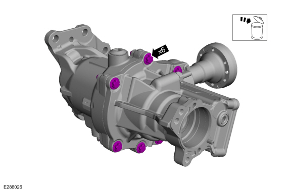
-
Remove and discard PTU case bolts.
 |
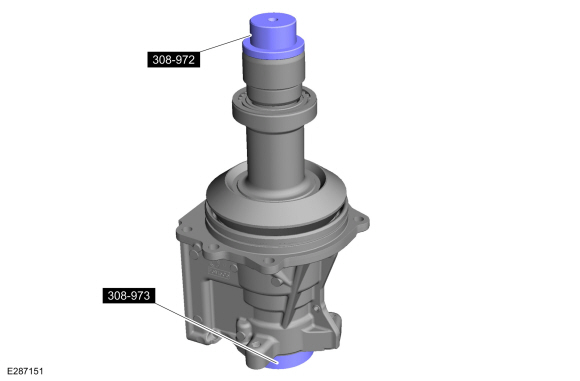
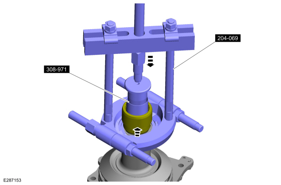
-
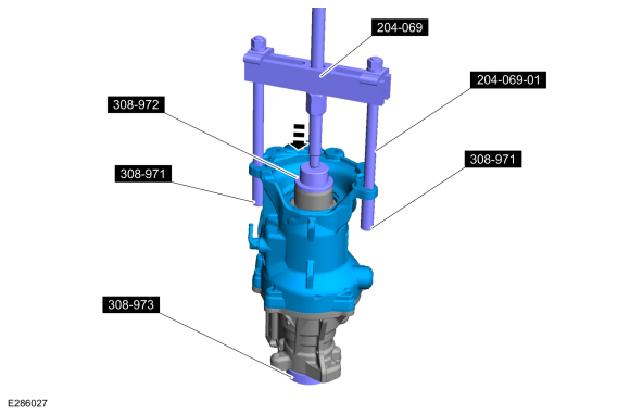
Intstall the special tools. Remove the casing.
Use Special Service Tool: 308-971 Remover, Input Sleeve. , 308-972 Installer, Input Sleeve. , 204-069 (T81P-1104-C) Remover/Installer, Front Wheel Hub. , 308-973 Remover, PTU Input Sleeve.
 |
-
NOTE: The bearing race and shim may come out when the seal is removed.
Using the special tools, remove and discard the LH seal.
Use Special Service Tool: 205-153 (T80T-4000-W) Handle. , 307-557 Installer, Ball Bearing.
 |
-
Remove and dicard the O ring.
 |
-
Position the internal components and side cover in the
press. Using the tool, push the input sleeve to neutral position to
release any pressure on the snap ring.
Use Special Service Tool: 308-972 Installer, Input Sleeve. , 308-973 Remover, PTU Input Sleeve.
Use the General Equipment: Hydraulic Press
 |
-
Check whether snap ring rotates freely in the groove.
.jpg) |
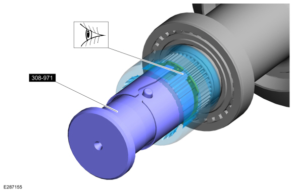
-
-
Install the tool in the connecting sleeve.
Use Special Service Tool: 308-971 Remover, Input Sleeve.
-
Rotate the tool until the teeth or fingers drop into the snap ring end gap.
-
Install the tool in the connecting sleeve.
 |
-
NOTE: The bearing separator should be installed loosely under the connecting sleeve. Tightening the bearing separator against the PTU input shaft will cause damage to the input shaft splines as the connecting sleeve is removed.
If the snap ring does not rotate freely, use the tools as per the graphic to pull the input sleeve up till it’s tight on the snap ring.
Use Special Service Tool: 308-971 Remover, Input Sleeve. , 204-069 (T81P-1104-C) Remover/Installer, Front Wheel Hub.
Use the General Equipment: Bearing Separator
 |
-
-
NOTE: The bearing remover should be loosely installed under the sleeve.
Install the tools as per the graphic.
Use the General Equipment: Bearing Separator
-
Remove the input sleeve.
-
.jpg) |
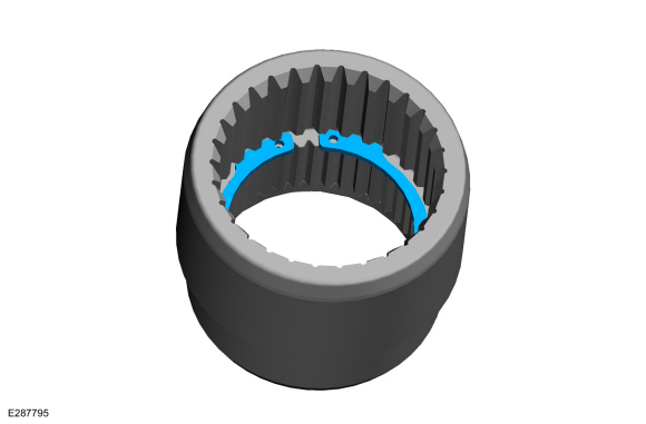
-
Remove and discard the snap ring.
 |
-
Remove the discard the O ring.
 |
Installation
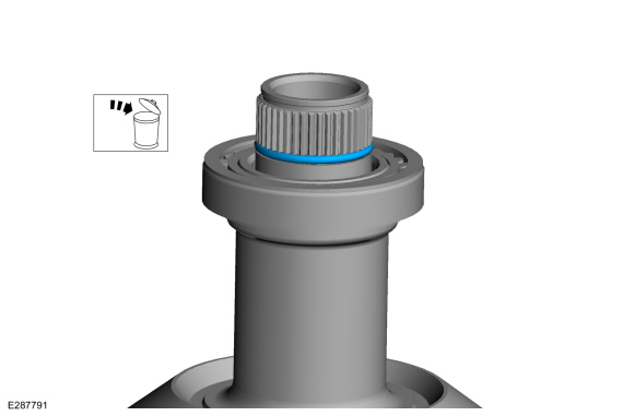
-
Lubricate and install the new O ring.
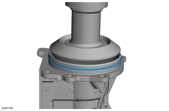 |
-
Lubricate and install the new O ring.
.jpg) |
-
Install new PTU case bolts.
Torque:
Stage 1: 22 lb.ft (30 Nm)
Stage 2: 50°
.jpg) |
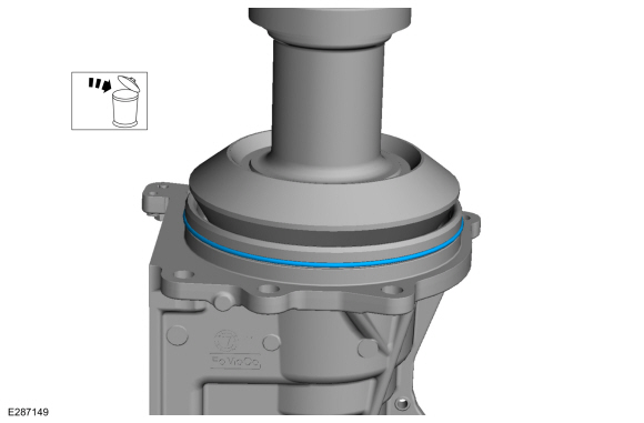
-
Using the special tool, install the LH seal.
Use Special Service Tool: 205-153 (T80T-4000-W) Handle. , 308-968 Installer, Input Shaft Seal.
 |
-
Install the new snap ring.
-
Inspect outer sealing surfaces for wear or damage. Install a new sleeve as necessary.
-
Lubricate and install the new snap ring.
-
Position the snap ring with the end gaps as close to
the center as possible, push down/outward on the snap ring opposite the
end gap.
-
Inspect outer sealing surfaces for wear or damage. Install a new sleeve as necessary.
|
-
-
Set snap ring to proper depth.
-
Install the connecting sleeve on the input shaft.
-
Install sleeve installer tool in the connecting
sleeve. Place AUTO side down for 8F35/40 applications. Place MANUAL side
down for MMT6
Use Special Service Tool: 308-972 Installer, Input Sleeve. , 308-973 Remover, PTU Input Sleeve.
-
Place PTU in a press and press until tool bottoms
out. A click sound may be heard when snap ring fits on the groove.
Use the General Equipment: Hydraulic Press
-
Set snap ring to proper depth.
.jpg) |
-
Install the PTU actuator motor.
 Removal and Installation - Power Transfer Unit Actuator Motor
Removal
NOTE:
Removal steps in this procedure may contain installation details.
With the vehicle in NEUTRAL, position it on a hoist.
Refer to: Jacking and Lifting - Overview (100-02 Jacking and Lifting, Description and Operation)...
 Removal and Installation - Power Transfer Unit Input Shaft Seal RH
Special Tool(s) /
General Equipment
100-001
(T50T-100-A)
Slide Hammer
205-153
(T80T-4000-W)
Handle
308-777Remover and Installer, PTU Input Shaft Seal
308-970Installer, RH halfshaft Seal
308-973Remover, PTU Input Sleeve
Removal
With the vehicle in NEUTRAL, position it on a hoist...
Other information:
Ford Escape 2020-2024 Service Manual: Diagnosis and Testing - Four-Wheel Drive Systems
Diagnostic Trouble Code (DTC) Chart Diagnostics in this manual assume a certain skill level and knowledge of Ford-specific diagnostic practices.REFER to: Diagnostic Methods (100-00 General Information, Description and Operation). Module DTC Description Action AWD C0090:16 4WD/AWD Power Transfer Unit Actuator: Circuit Voltage Below Threshold GO to Pinpoint Test A AWD C0090:..
Ford Escape 2020-2024 Owners Manual: Tire Pressure Monitoring System Precautions. Tire Pressure Monitoring System Limitations. Viewing the Tire Pressures
Tire Pressure Monitoring System Precautions WARNING: The tire pressure monitoring system is not a substitute for manually checking tire pressures. You should periodically check tire pressures using a pressure gauge. Failure to correctly maintain tire pressures could increase the risk of tire failure, loss of control, vehicle rollover and personal injury. WARNING: Do not use the tire press..
Categories
- Manuals Home
- 4th Generation Ford Escape Owners Manual
- 4th Generation Ford Escape Service Manual
- Adjusting the Headlamps
- What Is the Speedometer. Fuel Gauge
- What Is the Tire Pressure Monitoring System. Tire Pressure Monitoring System Overview
- New on site
- Most important about car
Under Hood Fuse Box
Locating the Under Hood Fuse Box

Accessing the Under Hood Fuse Box

Copyright © 2024 www.fordescape4.com