Ford Escape 2020-2026 Service Manual / Powertrain / Engine / Fuel Charging and Controls - Turbocharger - 1.5L EcoBoost (132kW/180PS) – I3 (Y1) / Removal and Installation - Wastegate Control Valve Solenoid
Ford Escape: Fuel Charging and Controls - Turbocharger - 1.5L EcoBoost (132kW/180PS) – I3 (Y1) / Removal and Installation - Wastegate Control Valve Solenoid
Special Tool(s) / General Equipment
| Hose Clamp Remover/Installer |
Removal
-
Remove the air cleaner outlet pipe.
Refer to: Air Cleaner Outlet Pipe (303-12A Intake Air Distribution and Filtering - 1.5L EcoBoost (132kW/180PS) – I3 (Y1), Removal and Installation).
-
Remove the air cleaner.
Refer to: Air Cleaner (303-12A Intake Air Distribution and Filtering - 1.5L EcoBoost (132kW/180PS) – I3 (Y1), Removal and Installation).
-
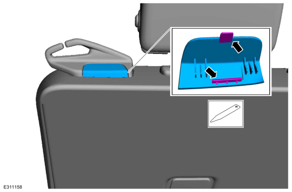
Disconnect the electrical connector, then detach the wiring harness retainers.
.jpg) |
-
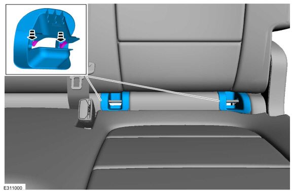
Disconnect the quick release coupling from the vacuum pump, then detach the hose retainers.
Refer to: Quick Release Coupling (310-00C) .
 |
-
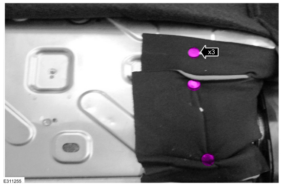
Detach the wiring harness from the wire harness retainers.
.jpg) |
-
Disconnect the turbocharger control hose, then detach the hose retainers.
Use the General Equipment: Hose Clamp Remover/Installer
 |
-
Remove the wastegate control valve solenoid retaining nuts, then remove the wastegate control valve solenoid.
 |
Installation
-
Install the wastegate control valve solenoid, then
install and tighten the wastegate control valve solenoid retaining nuts.
Torque: 89 lb.in (10 Nm)
|
-
Attach the hose retainers, then connect the turbocharger control hose.
Use the General Equipment: Hose Clamp Remover/Installer
|
-
Attach the hose retainers, then connect the quick release coupling to the vacuum pump.
Refer to: Quick Release Coupling (310-00C) .
|
-
Attach the wiring harness retainers, then connect the electrical connector.
|
-
Install the air cleaner.
Refer to: Air Cleaner (303-12A Intake Air Distribution and Filtering - 1.5L EcoBoost (132kW/180PS) – I3 (Y1), Removal and Installation).
-
Install the air cleaner outlet pipe.
Refer to: Air Cleaner Outlet Pipe (303-12A Intake Air Distribution and Filtering - 1.5L EcoBoost (132kW/180PS) – I3 (Y1), Removal and Installation).
 Removal and Installation - Turbocharger Oil Supply Tube
Materials
Name
Specification
Motorcraft® Metal Brake Parts CleanerPM-4-A, PM-4-B, APM-4-C
-
Removal
NOTICE:
The turbocharger compressor vanes can be damaged by even the
smallest particles...

Other information:
Ford Escape 2020-2026 Owners Manual: Air Conditioning System Capacity and Specification - 1.5L EcoBoost™
WARNING: The air conditioning refrigerant system contains refrigerant under high pressure. Only qualified personnel should service the air conditioning refrigerant system. Opening the air conditioning refrigerant system can cause personal injury. Use refrigerant and oil that meets the defined specifications. If you do not use refrigerant and oil that meets the defined specifications, it c..
Ford Escape 2020-2026 Service Manual: Removal and Installation - Spring
Special Tool(s) / General Equipment Vehicle/Axle Stands Removal NOTICE: Suspension fasteners are critical parts that affect the performance of vital components and systems. Failure of these fasteners may result in major service expense. Use the same or equivalent parts if replacement is necessary. Do not use a replacement part of lesser quality or substitute design. Tighten fa..
Categories
- Manuals Home
- 4th Generation Ford Escape Owners Manual
- 4th Generation Ford Escape Service Manual
- What Is the Tire Pressure Monitoring System. Tire Pressure Monitoring System Overview
- Opening and Closing the Hood
- Locating the Pre-Collision Assist Sensors
- New on site
- Most important about car
Vehicle Identification
Locating the Vehicle Identification Number
The vehicle identification number is on the left-hand side of the instrument panel.

Copyright © 2026 www.fordescape4.com